
MeArm Open Source Robotic Arm Plans, Kits and Information
RESOURCES TO GET YOUR MEARM ASSEMBLED AND MAKING MOVES
MeArm Assembly instructions.
MeArm V0.4 Original Build Instructions this is from the creators of the mearm project Benjamin Gray and Jack Howard. you can find a printable .pdf version of this build tutorial here. The original MeArm hardware design files can be found at Thingaverse.
Links to other MeArm Build Instructions:
Nice .pdf file with exploded assembly views.
Nice MeArm build with lots of pictures can be found here.
After building one Robotic Arm by following instructions from the above I have come up with my own abbreviated MeArm Build Instructions as presented here.
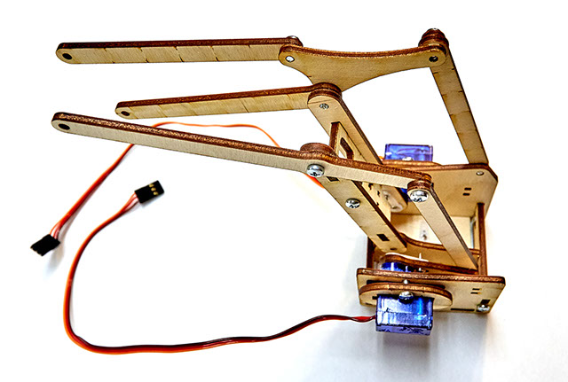
Looking at the MeArm robot arm fully assembled it looks like a pretty simple build and it is but with all the many little parts and different length bolts it can be a little confusing until it has been built up enough to start resembling the recognizable structure of the arm. I like to build several larger subassembly's to help me better visualize and simplify the complexity of the structure. the following images show the subassembly's I made from start to finish with one of my MeArm Roboric arm builds from a kit made by MicroBotLabs from amazon.
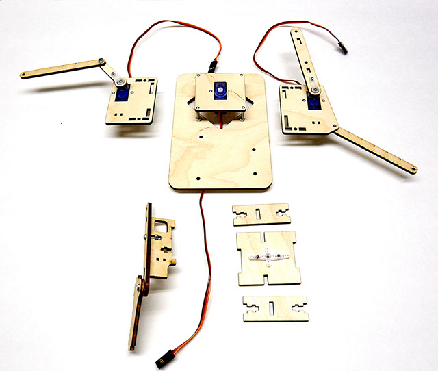
Base assembly and turret box assembly. pay attention to the motor orientation and the timing of the linkage that connect directly to the servo motors output gear. HOT TIP! all bolts that function as a pin to allow rotation should be tightened and then backed off to allow free movement with very little resistance. also make sure you have your orientation and timing right as this is hard to adjust once this portion of the robotic arm is assembled.
Turret box assembled. HOT TIP! All the bolt lengths are sized to match the material thickness or slot cut out exactly so if you find that a bolt sticks out to far or does not go the full length of the material thickness then you probably have the wrong bolt length, try another one.
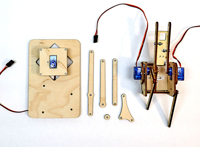
Next step is to add the 5 pictured link pieces to arm assembly.
Here is the arm assembly with the 5 additional link pieces. pay attention to their orientation and to what side they are mated.
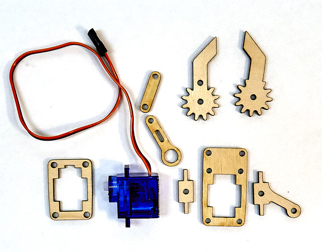
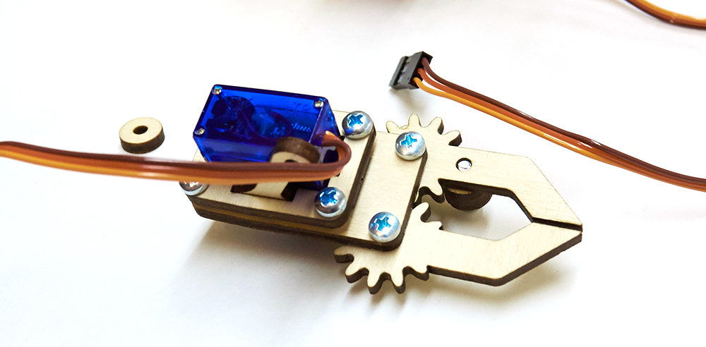
All the parts required to assemble the MeArm claw.
NOTE: Somehow I left out 2 round spacers that should show in this picture, they are also part of the claw mechanism.
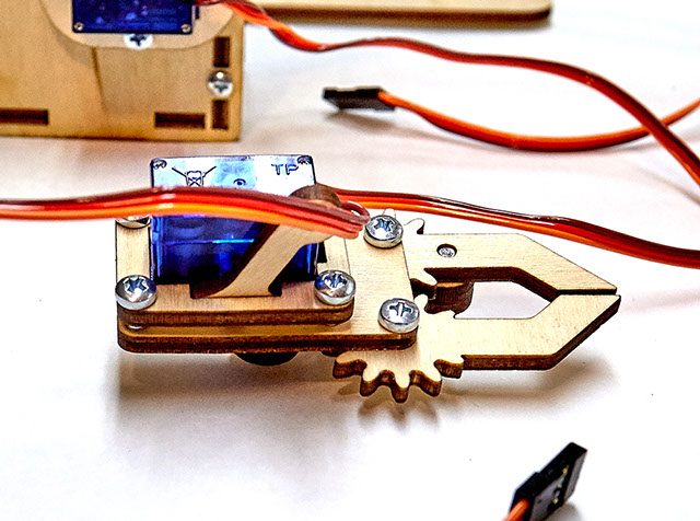
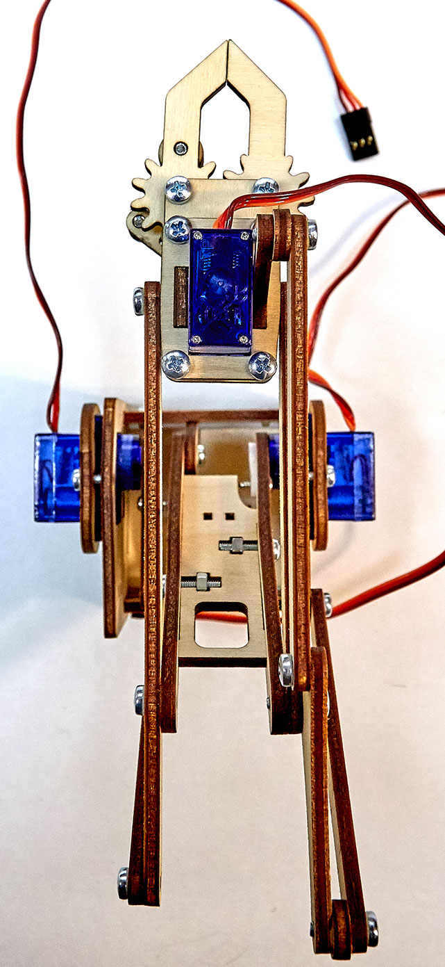
And the robotic claw mechanism fully built. see the next picture for an alternate view.
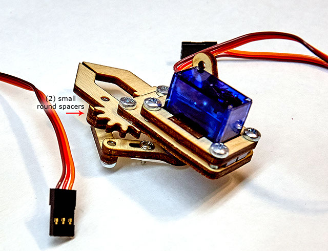
Alternate view of the robotic arm claw mechanism showing the two round spacers location.
The claw is installed onto the arm linkage with 3 bolts. note the small round spacer used on the top bolt.
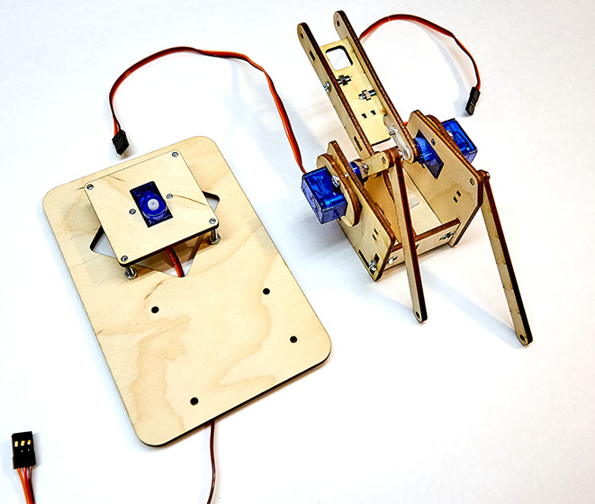
Almost have the mechanical structure complete! we just have one more step, installing the complete arm linkage onto the base as shown in the next picture.
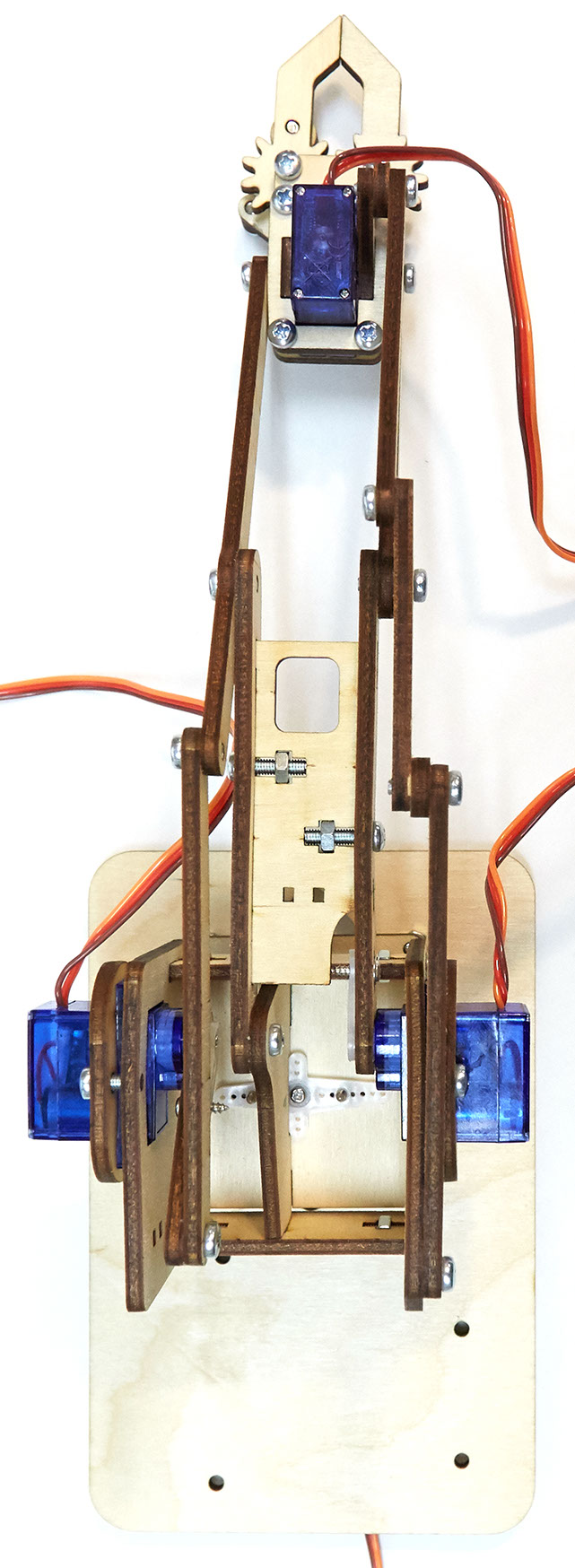
The MeArm turret box simply slides onto the base servo motor drive gear and is held in place by a small screw that came with the servo horns (small white plastic linkage that comes with the servo motor). before attaching the screw make sure that the servo motor is about half way threw its 180 degree rotation and attach the arm in the same orientation as shown in the above image. Congratulations you now have a complete mechanical MeArm assembly! Next step is to wire up an Arduino micro controller and get it ready to make some moves with the MeCon motion control software.
License